PID Controlled Homebrew RIMS System
Before I built my first RIMS system, I had an idea about what it was all about and how it compared to a HERMS. If you don’t already know, the basic difference is the direct and indirect heating of the wort.
Things a RIMS System Will Do:
- A recirculating heat infusion mash system makes it really easy to hit and maintain mash temperatures. As a bonus, you get to control it all from a shiny control panel with lights on!
Things I Didn’t Realise:
- You can get ultra clear wort by constantly circulating the wort through the mash bed (makes perfect sense when you think about it).
- I also didn’t realise that a PID (Potential Integral Differential) controller (I got an InkBird VH version) is different to an InkBird that you control your temperature controlled fermentation fridges and Kegerators with (who knew…? Just me then?).
How Do I AutoTune My Inkbird PID Controller?
Auto-tuning isn’t always as described in the InkBird literature. The user manual describes how to use the autotune function on the first time you power it up. It does not tell you how to access it if you’ve already powered it up to check and test your system wiring, as 99.9% of people probably will. That said, I imagine there’s a fair few people left scratching their heads about how they now calibrate their shiny new RIMS system. This is where crowdsourced information, and lessons from vloggers & bloggers, come in handy.
I enjoy the creative side of homebrewing. I like to create a new system from parts, I love the fact there’s always a lesson to learn, and (philosophy warning) think that learning from mistakes, is what life is all about.
I do like to try to share the love, so others, like you, can search and find the relevant information to end your own homebrewing pains. This is where Google keywords really come in handy. If you want to calibrate your InkBird PID controller using the autotune function, then this YouTube video could well be what you’re looking for. Go check it out below:
(Citation: Shout out to Rory Paul for making, and sharing, this video on his YouTube channel. Enjoy, subscribe.)
An Overview of Different InkBird Temperature Controllers
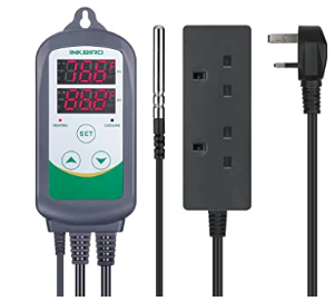
The image below shows (left to right) an ITC-100VH with 25A SSR, heatsink and Thermocouple – this (or a comparable unit) is what I’d suggest you want to control your RIMS system. The image on the right is the InkBird ITC-308 these units are rated at 10A and are NOT suitable for heating a 3kW heating element, you’d probably melt it. We all know and love the ITC-308 for controlling our Kegerators and fermentation fridges (maybe even your HLT with a lower wattage element?). You may have an STC-1000 that you can mount in place and use in the same way as the ITC-308.
 |  |
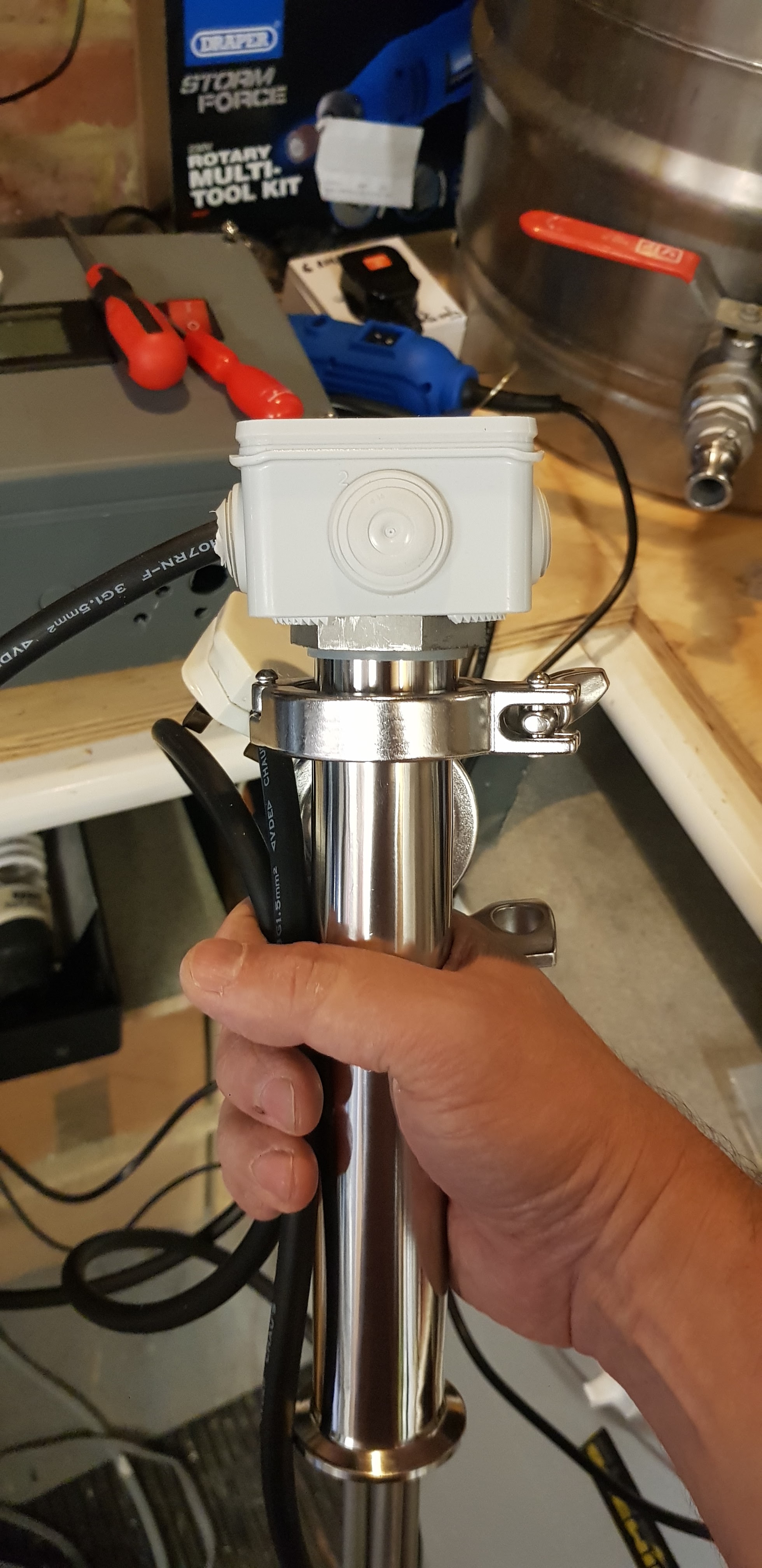
RIMS Tube Overview
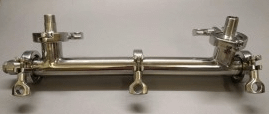
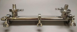
I recently bought a RIMS (Recirculating Infusion Mash System) Tube (see below). This version has tri-clamps that allows you to disassemble it for a deep clean and to scrub the heating element.
Why A RIMS System?
I wanted the RIMS system to help hit consistent mash temperatures. I’ve struggled to hit mash temperatures after updating to a 50l Bergland stainless steel mash tun, so I wanted a solid solution that would allow any mash rest. With this in mind, I asked around and the ACB homebrew community came through with answers.
Ashley, mentioned that he’d been using a RIMS tube and PID system, purchased from Brewbuilder. My interest came after reading:
RIMS uses “continuous recirculation at a more exact mash temp gives you a lovely clear wort and sets up a terrific filter bed in the grains.”.
This almost immediately set me about looking and building a picture of what I needed to create my own RIMS system.
I love a project, but decided that after seeing many options available, including using 1″ stainless steel threaded pipe, T-pieces and various reducers to make a 100% homemade RIMS tube and control system. The ease of use and ability to easily break down the RIMS tube on offer from Brewbuilder was more than worth the outlay. I did decide to take on making my own PID controlled system and also wanted to integrate power control for my Blichmann Riptide pump for ease of use.
After a few emails and recommendations from Lardy, of Brew Builder, I bought the component parts for the main RIMS tube. The parts list can be found here.
What is the Stainless Steel RIMS Tube?
The RIMS tube I bought from Brewbuilder is a 2-part stainless steel tube. It’s held securely with a set of tri-clamps and silicon seals. To complete the RIMS tube I also bought a 3 kW Low Density 1” BSP threaded heating element and 30 mm PT100 ¼” BSP threaded Thermocouple. The Thermocouple supplies temperature information to the InkBird PID Temperature Controller Thermostat ITC-100VH.
What is a PID Controller and How Does it Work?
The InkBird PID Temperature Controller Thermostat is a model: “ITC-100VH” PID controller. It works by reading real-time temperature information from the PT100 thermocouple. This PID I bought comes with a standard K-type Thermocouple. It also comes with a 25A SSR (Solid State Relay) and black heatsink. The SSR is the main switch that controls the switching of 240V power on and off to the heating element. The SSR sits on a black Heat Sink to dissipate heat from the SSR. Once the user-set temperature drops below the set threshold, the PID sends a 12V signal to activate the SSR, which completes the circuit to send 240-volt power to the heating element applying more heat when it is demanded.
Why Use a RIMS Tube?
When I was chatting about RIMS, I was told that: “A RIMS tube can give you extraordinarily clear wort”. I wanted to do this and create the best wort possible for the yeast to chew on. I also wanted to create and build my own RIMS and control system – why!? Well… who doesn’t like a project, eh?
With RIMS you constantly recirculate the wort through the mash. It lets you control the temperature of the mash. It also reduces hot spots in the grain bed and aids in wort clarity. Using a RIMS tube means that you are constantly circulating wort through the tube over the heating element, monitored the entire time by a Thermocouple (PTC100 in my case).
*Slack is a community chat app, like WhatsApp.
Build or Buy a Bespoke RIMS System?
Safety Warning/Disclaimer
Before you decide what you want to do. Please understand that UK mains electricity is highly dangerous and can kill you or burn your house/shed/garage/brewery down! You should only work with mains electricity if you know what you’re doing and at the very least, always get your work and your supply checked by a qualified Electrician before you run it up. It is very important that a RIMS system is correctly isolated and used with suitable failsafes in place.
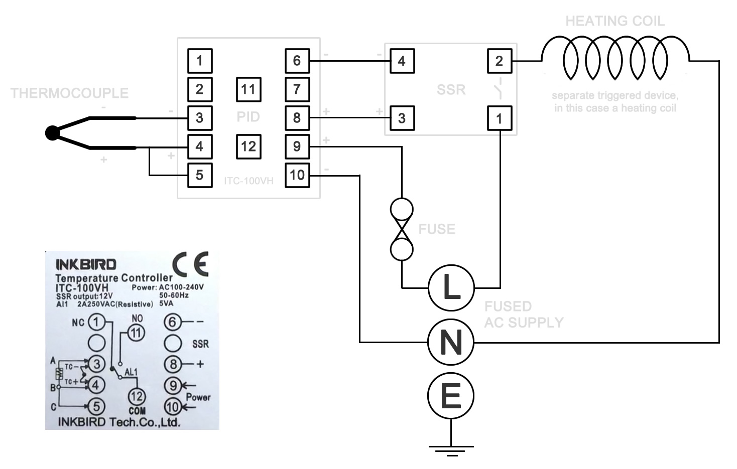
RIMS Wiring Diagram
Right, now the warnings are out of the way, I’ll say this much, building your own PID control system can save you a ton of money and is a hella-fun to build.
The basic wiring diagram is as below. If, like me, you use a PT100 type thermocouple, it’ll come with 3 wires 2x red and a white or yellow. The 2x reds go to pins 4 and 5, so you don’t need to worry about bridging the pins (4,5) this is for K-type thermocouples.
Wiring the Heating Element
As mentioned before the heating element takes the brunt of the power requirements in this system, so it need the most respect.
Isolation
As the RIMS tube is likely to be metal, you need to ensure that it is isolated from the power supply. Using a plug-in RDC to constantly monitor for power faults is one failsafe I’ve employed to protect myself from electric shock.
Instead of the supplied metal shroud, I used an waterproof junction box, intended for use outside.

Use a Suitable Cable
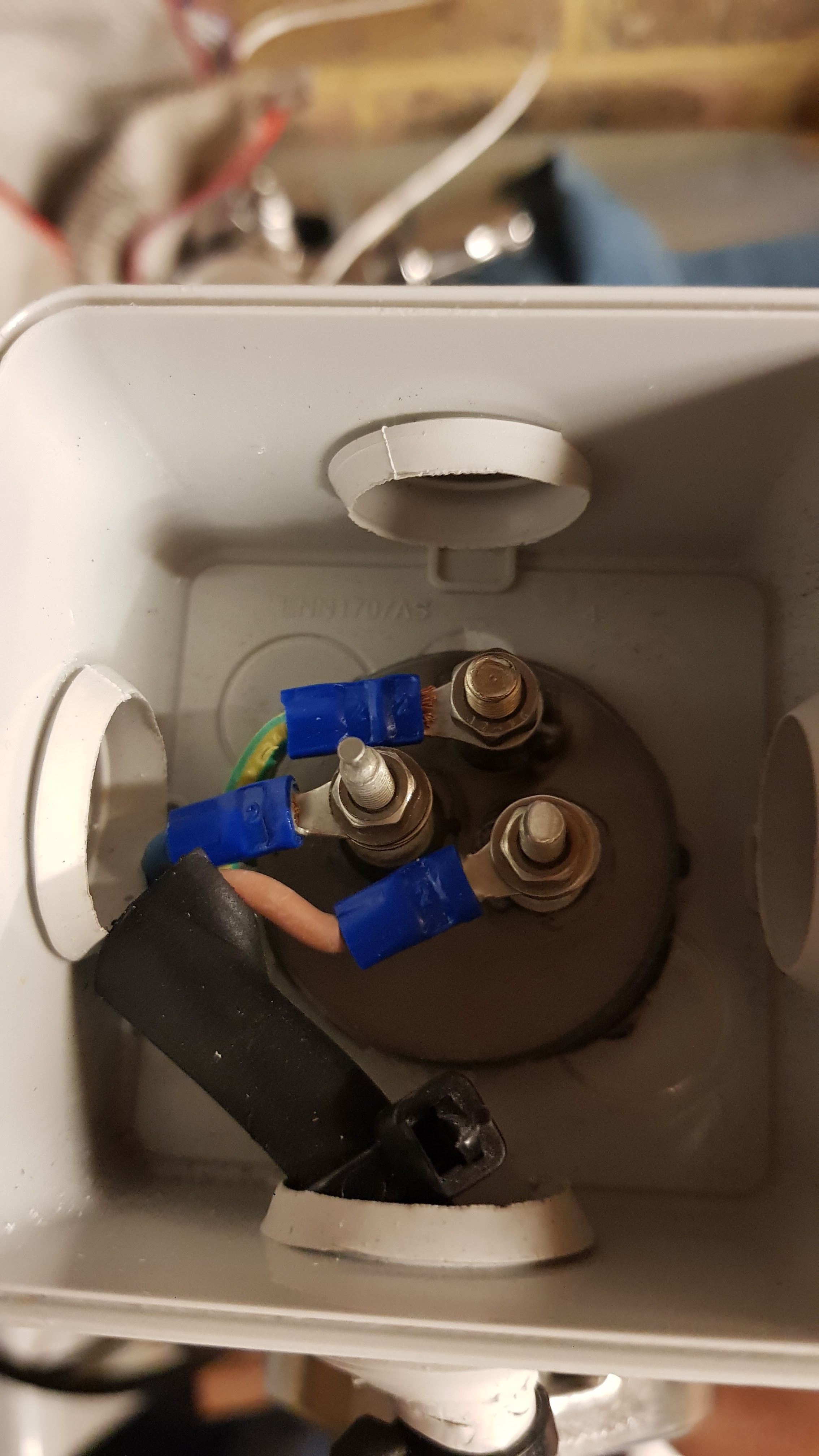
I used 2.5mm high temperature flex cable to supply power from the SSR to the heating element with sleeved, crimp-on ring terminals to connect to the element’s 3x terminals (see image below).
[Update: after 2 uses I noticed a funny, acrylic aroma when I turned the unit on, so I checked it out and found that the sleeved ringer terminals’ sleeve had melted away. To remedy this, I cut the cable shorter and used the washers on the live and neutral poles to secure the cables in place and not had any issues since.]
Connecting Power
As the image below shows, the BrewBuilder supplied heating element has 3x threaded posts to connect to. 2x of the terminals run along the centre axis, which correspond with the heating element. This is where you connect live and neutral in either polarity, AFAIK it doesn’t matter. The earth terminal is situated above/below.

Connecting to the PID Controller
Ensure that the other end of the element power supply cable is commoned up (connected) with the mains 240V in supply earth. This is so the element is actually earthed. For my common wiring, I used a 20A terminal junction box. These have enough capacity, are fairly small and easy to work with and to fix in place.
PID Control – What is PID Control?
The main idea for PID control is that you interrupt the mains connection to the heating element using the SSR. This is how the PID controls the switching of the power on/off to the SSR, maintaining the set temperature. The thermocouple provides the temperature feedback to the PID, which lets it know when to cycle the power on/off – depending on your preset parameters.
Do You Want to Build Your Own Control System or Buy Off the Shelf?
Once you find out and decide if you want a RIMS system yourself, you’ll need to decide how you’re going to go about either buying or creating your own RIMS system. I spent some time researching and finding out what I needed to do before jumping in. I found Gerorge of Barley and Hops on YouTube a hive of information (even if he is an acquired taste).
RIMS System Parts List
As advised by Ashley, I sourced my RIMS tube components from www.brewbuilder.co.uk. For the control system I looked around and bought the components to make my own PID control system.
Electrical Capacity
No matter how you decide to proceed, you’ll need to understand if your home/garage/workshop/shed brewery fuseboard and wiring can take the electrical demands your chosen heating element will put on it.
Considerations – Get Professional Opinion
Depending if you have other electrics running, you’ll need to ensure you have the capacity to run an electric system. I’m lucky and already had a 32A supply to my garage. A lot of garages etc., with power, were only wired with the intention of powering lights and maybe a tumble drier and/or fridge. These are often run from a 16A circuit from the main fuse board. I’d highly recommend seeking the advice of a qualified electrician to make sure your supply and MCB are up to the task (FYI: I’m not qualified).
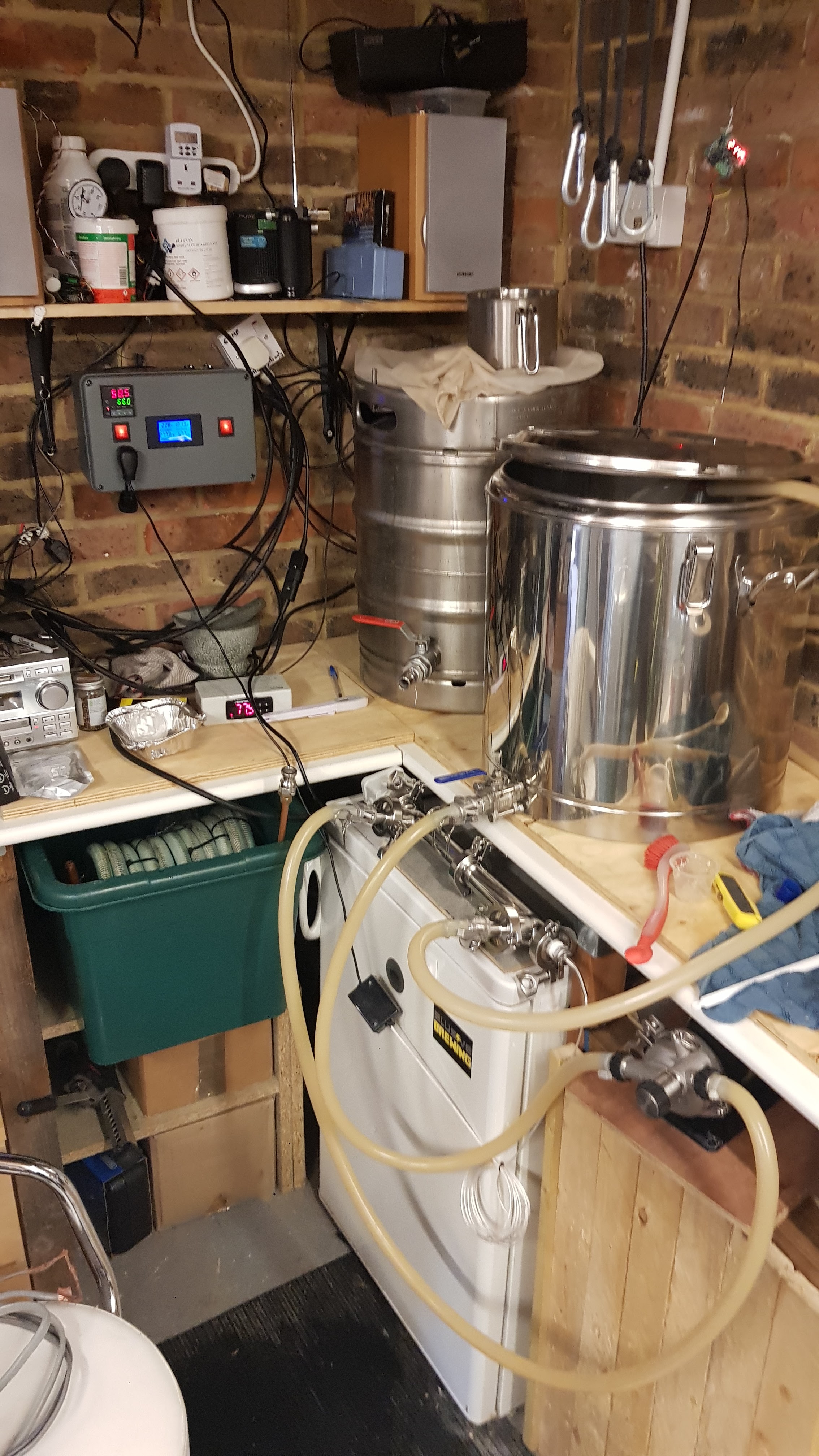
My Garage/Brewery Electrics
In my garage, where my brew-bench is (not sure you could call it a brewery?) I have 2x 32A circuits:
- General garage sockets on a 32A ring main that runs:
- 2x 2.4 kW HLT elements = 20A (spread over 2x separate plugs).
- Brewing specific – 32A radial with 2x double sockets that runs (at separate times):
- 3kW Ultra Low Density (ULD) element = 12.5A
NOTE: ULD elements provide a larger surface area to help avoid scorching.
- Blichmann Riptide pump <1A
- Fermentation Fridge controlled by an InkBird ITC-308W.
NOTE: The ITC-308W is great. The “W” means it’s the wifi version. This is very handy for remotely changing settings, like ramping temps for diacetyl rests. I use the remote function of the ITC-308W a lot. It has handy temperature charts, shown over time, which allows you to check if your yeast is kicking off. I find the temp will spike a bit as active fermentation begins. It also allows you to make changes when you forget to do them before leaving for work.
I also run a 12V bus that means I can run low voltage items, like the 12V clip-on cab fan that distributes the steam around the garage from the kettle. It also powers the digital thermometer that I use for telling the output of my homemade Counterflow Chiller (CFC). I also wrote an article on building your own CFC.
RIMS Parts:
Control Panel Parts – Various Sources:
- InkBird PID Temperature Controller Thermostat ITC-100VH
- This came with a standard K Thermocouple and 25A SSR with a black Heat Sink.
- IP66 Waterproof Electric Box for control box
- Volt Amp Meter – not required, but a nice extra to see how much power your using
- 2x 240V Rocker Switches for mains PID and Pump power
- 1.5mm electric flex cable 10m (Screwfix)
- 5mm ring crimps (Screwfix)
- Suitable sized Waterproof insulated box for heating element isolation (Screwfix)
- Various electrical junction boxes and Wago connectors to connect cables
Building A PID Control Panel is Fun!
If you decide to build your own control panel, first up COOL! But if you do build yor own, please make sure you’ve read the warnings and are aware that you’re working with mains electricity and all the risks that entails.
As long as you’re careful, then: Building your own PID control panel is fun! I really enjoyed making mine. And now I’ve used it, I love it. Automating your mash means you can achieve any rest temperature you want to – BOOM!
For my RIMS system control panel I made use of an InkBird ITC100-VH PID to accurately and safely control the heat. PID stands for Proportional Integral Derivative. It works as a feedback mechanism, monitoring the system and applying specific controls when necessary (basically, this means turning the heating element on/off). PIDs are often used to control speed, flow and pressure. In this case we’re interested in temperature.
A Bit About The PID Controller
The PID takes in 240V AC (UK mains electricity and outputs 12V to the 12V side of the SSR. This effectively switches the SSR to make the connection to enable the heating element to do its job.
Heating Element Wiring
The heating element wiring does need to be up to the job. I used a 1.5mm flex cable for my wiring.
Cutting Out the Control Panel
I also bought myself a Draper rotary multitool to help with cutting the apertures for the PID control, AMP Meter display and switches. I do need more practice with this particular tool, but it did a job and I’m only really interested in the box being functional for this project.
Wiring
With the control box cut out and fitted with the PID, AMP Meter and switches, that just left the wiring up. This is where the wiring diagram came in handy. For me the most important part was ensuring that the 240V AC mains cables were capable of carrying the current required. I also spent time ensuring that all wires were commoned up (isolated from each other) using a terminal block so all the live wires were isolated from the neutrals and earth wires etc.
NOTE: I’m not going to show my wiring or tell you how to do it, I’m not qualified to.
Electrical Isolation
The 3kW heating element is isolated with sheathed ring terminals crimps. These are protected in a small waterproof electric junction box that helps to further isolate the mains electricity.
[edit: After the second use, I found that the load was far too much for the crimp terminals – they were showing signs of heat stress and throwing off an acrid aroma when the element was powered. After taking professional advice, I removed them and used bare wires, carefully twisted around the terminals and secured in place with the bolts and nuts and isolated with electric tape. It’s been great ever since.]
 |  |
Brewery/Garage Electrical Capacity
My brewery has a dedicated 32A supply with robust 5 mm twin and earth wiring, it’s over-specced on purpose.
The 3kW RIMS heating element runs at 12.5A at full tilt, which is only for short spells. The RipTide pump runs at less than 1A. I’m running the control panel off a single 13A plug, so there’s not a lot of leeway to trip the fuse. If I find I have any issues, I can easily run another mains in from a separate plug. I wanted to control the pump from the control panel too.
[edit: I took professional advice from my brother-in-law, who’s a spark’. He recommended that I run a 32A ring main in my garage. This was to spread the load between plugs. I now have. a much more robust garage brewery, electrically speaking at least.]
Some Links to Videos Of YouTube RIMS Examples
FAQs
What is A RIMS System?
A RIMS (Recirculating Infusion Mash System) system uses a direct heat source to heat the wort as it is constantly recirculated through the gain bed. The heat source can be electric or gas. The wort is heated as it is pumped over the heat source, the heated wort is returned to the grain bed, raising the temperature of the mash to the required temperature. The RIMS system is controlled by a PID controller. Temperature feedback is supplied by a thermocouple.
What Do I need to Run a RIMS System?
To run your RIMS system you will need a RIMS tube capable of holding a powerful heating element 2kW to 3kW and thermocouple that will supply the control system with accurate temperature information. You will also need a pump with suitable hoses and fittings to maintain a constant flow of wort over the grain bed and through the RIMS tube. You will also need a control system capable of supplying your heating element with enough electricity.
There are optional items you can also incorporate to your control system, like switched pump controls, Amp-meters to see power use and mains key switches. The list is endless, you don’t need the extras to have a running system.
Would a HERMS System Suit me Better?
If you have a few metres of 10mm copper pipe and a pump capable of pumping your wort around the copper coil, you could, in theory, use an InkBird to maintain a set temperature in the HLT, which is roughly the inverse of a RIMS system, being in-direct rather than direct heating of the wort. Using the copper coil immersed in your HLT with wort circulate through it will help you maintain a mash rest temperature and allow you to change the rest temperature.
Why Would I Want to Use a RIMS System?
If you have an inefficient mash tun or use a picnic hamper type mash tun then using an electric RIMS tube is going to improve how you maintain your mash rests n-end. The constant recirculating of the wort through the mash bed helps to set the grain bed and filters the smaller particles over the time it’s running resulting in you running uber-clear wort to your kettle. Who doesn’t want that – right!?
Where Can I Buy a RIMS System?
You can buy an off-the-shelf RIMS system to fit in to your existing brewing system. This is likely to cost around £600-£700, which is great. I like working to build my own kit for the experience it also helps to save a few quid.
Can I Make My Own RIMs System?
If you’re more adventurous or engineering minded, then you can easily build your own system. I’ve put a list of parts together that you can use to source your own parts. Read on to see the list.
Credits/Links/Disclaimers
Disclaimers
As stated earlier – I’m not a qualified electrician. 240V AC (UK mains electricity) is dangerous. Mixing electric and water is also a bad idea. This blog is not a procedural guide to building your own system. It is only intended as a guide to help shortcut your information gathering for your own RIMS system.
Please don’t play with electricity if you’re not confident or qualified to do so (don’t mistake confidence with naivety or stupidity). Please, ALWAYS get your work checked by a qualified electrician before you run your system. A heating element with a 240V supply that’s not correctly isolated is potentially LETHAL!
Links
None of the links in this article are affiliated. They are all part of my own research and a result of information gathering. I’m not recommending that you go to any of them to buy anything. I’ve tried to give my honest opinion from my own experience. Unless I’ve highlighted any issues, assume that I’ve had a good experience. For this project, other than time taken to get a lump of time to create the system, I can’t complain (but I’ll find an excuse or create a reason tom, somewhere along the line).
Credits
Credit to https://www.vegoilguy.co.uk/pid.php for the wiring diagram and other information that I found very useful to follow to get my system up and running.
Gerorge of Barley and Hops on YouTube – a very interesting character and also a hive of information – may be an acquired taste, but helped me.
www.homebrewbuilder.co.uk for help, advice and supplying an awesome RIMS tube and associated equipment.
PID Controller description wikipedia.
Appreciate this is a long shot as this is an older post. I am building pretty much exactly this setup and I’m having issues with the PID. Can you let me know what settings you used for the ITC-100VH. I’ve had a read through the instructions and they are….challenging. thanks in advance.
Hi, thanks for your question. It was a while ago since I calibrated my unit. It’s been working fine for me using the “autotune function”. I’ve added the below link to the post to the YouTube video I used to calibrate my ITC-100. I used the autotune function to calibrate. The literature isn’t great. Hopefully this helps you? All the best, Rich
[edit: YouTube link: https://youtu.be/AxY78XjBaHs ]